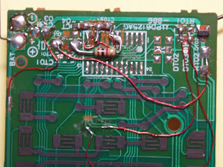
This is the PCB found in the remote. The single IC chip is removed together with all the unnecessary components.
I keep the SMD transistor for use in the Joule Thief itself. Also the small capacitors.
The foil are cut to support the Joule Thief circuit.
A 1/4 watt 1K resistor is soldered in place.
Note the cut near on of the printed circuit switch.
This is the EQ button on the remote. This is chosen because it is in the center of the cursors buttons and is easy to remembered. Thin wires connect this key switch to the base of the SMD transistor and on end of the Joule Thief coil.
I need to cut the foil that supplied the normal Infra red LED in the front because the polarity are reverse and I do not want to run a long wire to the front for fear that this may interfere with the seating of the rubber keypads on the printed circuit key switches


No comments :
Post a Comment